Hans Walser
SEMI CUBES
Abstract: A cube cannot be transferred with ruler and
compass into a cube of half the volume. On the other hand, there are a number
of easy-to-construct figures that halve the cube volume. Symmetry
considerations play an important role here. With these figures, the space can
be filled without gaps and without overlap. We will discuss the difference
between the static "fit in" and the dynamic "fit into". We
are working in the dimensions two, three and four. For the production of some
figures the "monkey saddle" is used. Similarly, we can work virtually
with 3d origami. Some examples are illustrated with paper models.
Bisecting the cube
Examples
For the keyword “bisecting the cube”, we first think of the problem of finding a cube that has half the volume of a given cube. This problem - it is the equivalent of “doubling the cube” - cannot be solved with ruler and compass. On the other hand, it is very easy to find figures with half the cube volume, which are not cubes themselves (Fig. 1). For this type of cube bisecting, see Walser (2018), pp. 93-108.
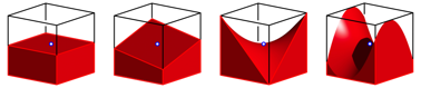
Fig. 1: Half cube volume
The monkey
saddle
Figure
2 shows the so-called monkey saddle and a cube placed on a vertex. The monkey
saddle with the equation ![]() has a
three-fold rotational symmetry with respect to the vertical z-axis. But this also applies to the
cube when a spatial diagonal is on the z-axis.
has a
three-fold rotational symmetry with respect to the vertical z-axis. But this also applies to the
cube when a spatial diagonal is on the z-axis.
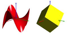
Fig. 2: Monkey saddle and cube
And now we use the monkey saddle to cut away the upper part of the cube (Fig. 3). Thus we receive half a cube. The blue counterpart is point symmetrical.
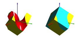
Fig. 3: Intersection of the cube with the monkey saddle
The monkey saddle can be seen as a graph of a function in x and y with z-directional function values. Therefore, each parallel to the z-axis cuts the monkey saddle exactly once. Thus, we can disassemble the two half cubes of Figure 3 in the z-direction without friction and reassemble them without collision (Fig. 4).
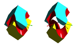
Fig. 4: Moving the two half cubes
Fitting in the
coordinate-system
Now we place one of the two half cubes in the Cartesian coordinate system such that one vertex sits in the origin and three edges on the coordinate axes (Fig. 5).
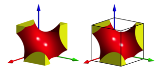
Fig. 5: Fit into a Cartesian coordinate system
Then we reflect the figure about the coordinate planes and get a twelve-footed figure (Fig. 6).
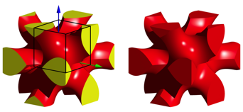
Fig. 6: Mirroring at the coordinate planes. Twelve-footer
Space-Filler
The twelve-footer is space-filler. With congruent twelve-footers, we can fill the space without gaps and overlaps. However, one has to proceed in the right way.
Attempting to assemble four twelve-footers in a square (Fig. 7, left picture) and then pushing a fifth one into the gap from above fails. The blue twelve-footer collides with the others.
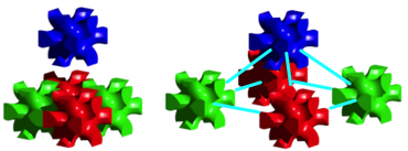
Fig. 7: False and right procedure for fitting
Instead, we must first place the five twelve-footers so that their centres form a square based pyramid whose height is half as long as the bottom edge (Figure 7, right picture). The sloping edges then are in the direction of the cube diagonal along which a collision-free moving is possible according to Figure 4. The fitting together of the five twelve-footed has to be done simultaneously. This requires five hands. Figure 8 shows the result and a larger version.
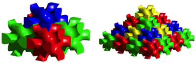
Fig. 8: Pyramids of twelve-footers
An edged monkey saddle and a star
Figure 9 shows a cube bisecting by an “edged” monkey saddle.
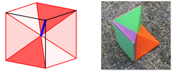
Fig. 9: Edged monkey saddle
The construction is the following. We divide a cube from the centre into six pyramids, each of which has a face of the cube as its base, and the centre of the cube as the top. In Figure 9, three of the six pyramids are inserted so that each has one side triangle in common with the two others. The figure has a three-fold rotational symmetry with respect to the blue marked diagonal of the cube. The dihedral angle at the edges of the monkey saddle is 120 °.
Through mirrors, we get a star with twelve points (Fig. 10). This star is half a cube again.
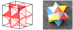
Fig. 10: Star
The star is also a space-filler (Figure 11). The assembling is easily possible.
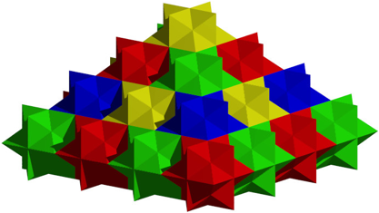
Fig. 11: Star pyramid
A cross and its complement
The cross
Figure 12 shows a monkey saddle with right-angled edges. Through mirrors we get a 3d-cross. This cross can be seen as a half cube as well.
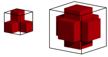
Fig. 12: Half cube and cross
The 3d cross is a space-filler (Fig. 13). The assembling of the crosses is easily possible.
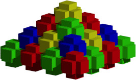
Fig. 13: Pyramid of crosses
The complement
Now we turn the saddle of Figure 12 that we can see it from the back (Fig. 14). Through mirrors, we get a figure, which is the complement to the cube of the cross of Figure 12.
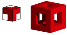
Fig. 14: Complementary situation
This figure is also a space-filler (Fig. 15). It fills the space inside the pyramid without gaps and overlaps. However, the individual components are completely linked. It is not possible to build the pyramid from individual loose components without tearing up the parts. The parts fit into each other, but we cannot fit them.
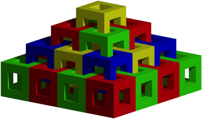
Fig. 15: Fits. But cannot be adjusted
Excursus: A variant of the Menger sponge
The figure in Figure 14 leads to a variant of the Menger sponge. Figure 16 shows the first two fractalization steps.
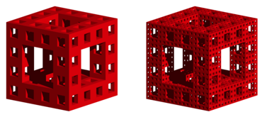
Fig. 16: Variant to the Menger sponge
Unlike the original Menger sponge, this variant has a rational fractal dimension, namely:
![]()
Static fitting and kinematic fitting in
In Figure 15 we saw the difference between static fitting and kinematic fitting in. Some more examples follow.
Puzzle
The puzzle of Figure 17 is almost done. However, we cannot fit the missing element in the upper right corner on the level of the puzzle. We have to take it off and adjust it from the top. We need the third dimension of the space.
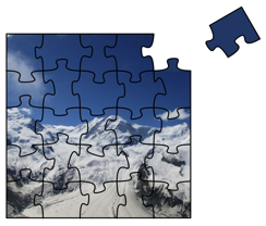
Fig. 17: One part still missing
In the example of Figure 18, the corner piece fits in the gap, but it cannot be pushed in.
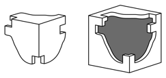
Fig. 18: Does the corner fit into the gap?
In four-dimensional space, the problem could be solved very easily. We could lift the three-dimensional corner into the fourth dimension and then push it in.
Problem with walnuts
Figure 19 shows three nuts each in two views. The first example is a common nut with a two-fold rotational symmetry. In the second example we have a three-fold and in the third example even a four-fold rotational symmetry. To find out whether the kernels also have corresponding rotational symmetries, the nuts would have to be cracked. That would be a shame about the rare nuts.
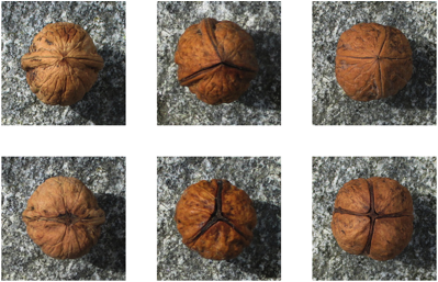
Fig. 19: Nuts
In four-dimensional space, the problem could be solved very easily. We could just take the kernel out into the fourth dimension. Figure 22 illustrates the situation one dimension lower. Two-dimensional nut kernels are obtained by lifting them out of the two-dimensional shell.
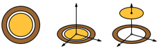
Fig. 20: Embedding the 2d-nut in the 3d-space
Origami in the 3d-space
Origami in the plane
Below are some examples of folding processes using the usual two-dimensional origami paper.
Figure 21 shows an origami cube consisting of six components.
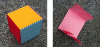
Fig. 21: Origami cube. Component
Figure 22 shows, as a simple folding process, how to fold the vertex in the upper left vertex to the lower right vertex. We assume the paper is yellow on one side and light blue on the other. From a square we get a two-layered half square.
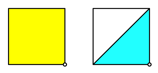
Fig. 22: Vertex top left to the vertex bottom right
Another simple folding process is to successively fold the edge midpoints or the vertices into the centre of the square (Fig. 23). In both cases we get a square.
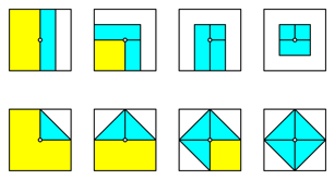
Fig. 23: Folding into the centre of the square
We transfer these folding processes to a virtual 3d origami.
Spatial origami
How is a 3d origami to be understood? For this we think of a cube, which we fold in four-dimensional space. The material for this cube still has to be invented. In Figure 24, the top left vertex is folded to the diametrical vertex.
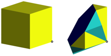
Fig. 24: 3d origami
Of course, this folding process can also be described purely in three dimensions. We halve the cube with by a normal mid-plane of a body diagonal and reflect one half on the other side.
Folding the face centres
By folding the face centres to the centre of the cube, we obtain a smaller cube after six steps (Fig. 25). It has half the edge length and thus one-eighth of the volume compared to the original cube. It has eight times the material density. Of course, this cube is a space-filler.
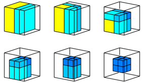
Fig. 25: Folding the face centres into the centre of the cube
Folding the edge centres
When folding the midpoints of the edges into the centre of the cube we need twelve folding steps. After the first four steps you will see a square-shaped house with a pyramidal roof (Fig. 26).
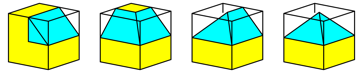
Fig. 26: Folding the midpoints of the edges into the centre of the cube
After another four steps, we again get a building with a square floor plan. It has a rhombic roof (Fig. 27).
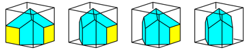
Fig. 27: What happens between the second and the third picture?
Such rhomboid roofs were built as tower helmets in Romanesque and Neo-Romanesque churches (Fig. 28).
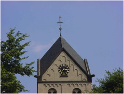
Fig. 28: Church in Krefeld
The last four folding steps lead to the rhombic dodecahedron (Fig. 29). The volume of the rhombic dodecahedron is one quarter of the original cube volume.
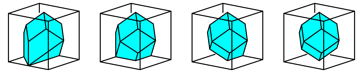
Fig. 29: Rhombic dodecahedron
The rhombic dodecahedron is also a space-filler. In Figure 30, rhombic dodecahedra approximate a sphere.
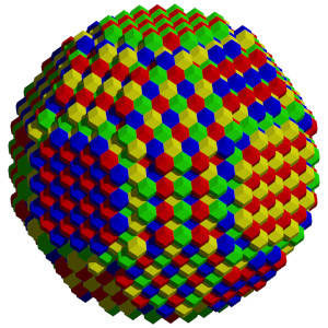
Fig. 30: Rhombic dodecahedra approximate a sphere
Folding the vertices
Folding the vertices of the cube into the centre of the cube results in a truncated octahedron (Figure 31). Its volume is half the cube volume.
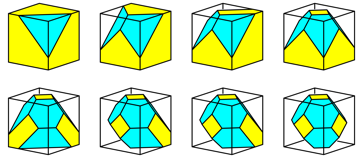
Fig. 31: Folding the vertices into the centre of the cube
The truncated octahedron is also a space-filler (Figure 32).
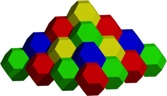
Fig. 32: Pyramid of truncated octahedra
References
Walser, Hans, R. (2018): Der Würfel. Ansichten
– Dimensionen – Modelle. Edition am Gutenbergplatz, Leipzig 2018.
ISBN 978-3-95922-102-3.
Walser, Hans, R. (2018): Halbe Würfel. IBDG, Informationsblätter
der Geometrie. Heft 2/2018, Jahrgang 37. S. 37-42.