The
following article is published:
Scott
Johnson and Hans Walser: The Pop-Up Octahedron. Mathematics in School. Vol. 25,
No. 5, November 1997, 2-4
Back in
1988 we published a set of Maths Resource pages on p0p-up polyhedra (Cassell,
1988) which were well received at the time. The 'toys' developed by the two
authors as described here take the art somewhat further. Of particular interest
is the fact that the principles employed can be applied to many other polyhedra
and this article complements another, more theoretical, article planned to be
published concurrently in our sister publication, the Gazette (]ohnson &
Walser, 1997)
by Scott
Johnson and Hans Walser
1
Introduction
In this
article we discuss how to build a mathematical toy. First we describe how to
construct a pop-up octahedron. This octahedron may be pressed flat into a
planar configuration and then when you either let go, or toss it into the air,
it pops (making a noise) into the shape of the regular octahedron. Figure l (a)
illustrates the entire spatial octahedron. The Figures 1 (b) and 1 (c) depict
the intermediate stages as you press it flat, by exerting downward pressure on
the top vertex (the North Pole) while holding the bottom vertex (the South
Pole) in a fixed position. The dark portions of Figures 1 (b) and 1 (c) show
the inner cavity of the octahedron which will be visible between the two edges
that separate as the model goes down into a planar shape (and, in fact, on your
finished model you will then be able to see the rubber band that makes the
model pop-up). Figure 1 (d) shows how the model looks in its flattened
position. In terms of our global description the model opens along a
longitudinal line, connecting the North and South Poles, running along edges of
the octahedron. The outer hexagonal part of the border in the flattened
position is part of the original equator.
Fig. 1 Pressing down
The
flattened situation consists of two layers with four equilateral triangles in
each layer. Observe that, since every angle of an equilateral triangle is 60°,
you have at the centre (where the two former poles now meet) a gap of 120°. If
we were to fill this gap with two additional equilateral triangles on the top
layer and two directly beneath those on the bottom layer we would form two
regular hexagons - and that model would not be deformable into a polyhedron having
these 12 equilateral triangles as faces. Such a model would either remain flat,
or would flex, along the six edges radiating from the center, in space. However,
if you added only one equilateral triangle on the top layer and one directly beneath it on
the bottom layer you can construct another pop-up polyhedron, which is known as
the pentagonal dipyramid shown in Figure 2(a). Although this 10-faced
polyhedron is not as regular as the octahedron (not all vertices are contiguous
with the same number of edges) it does have some interesting properties and
uses (it may serve, for example, as a random number generator for the ten
digits 0 through 9).
If,
instead of adding a triangle to each layer, you remove one triangle from each
layer (one lying above the other) you will be able to construct a 6-faced
polyhedron known as the triangular dipyramid shown in Figure 2(b). Again, this
6-faced polyhedron is less regular than the octahedron.
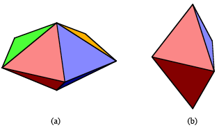
Fig. 2 Double pyramids
What
happens if you remove two contiguous equilateral triangles from each layer
(where they both lie above each) from the configuration in Figure 1 (d)? You
will have, in fact, four equilateral triangles. Why don't you get the regular
tetrahedron shown in Figure 3? If you don't see the answer to this construct
the configuration and examine it closely.
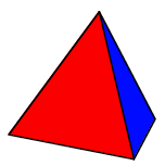
Fig. 3 The
regular tetrahedron
2
How to
build the pop-up octahedron
2.1 The triangular faces
What we
describe is how we built our models. However, you may find other materials that
work just as well. You should experiment and find out what works best for you.
We built
our models from foamboard (this is a 5 mm thick piece of foam covered with
paper on both sides), and sometimes from cardboard, or thin plywood (about 3 mm
thick). First you draw the required eight equilateral triangles on the
foamboard. Of course the size of these triangles is up to you, but all of them
need to be congruent. We built our models with an edge length of 10 cm. To cut
the foamboard we used a sharp knife - a Swiss army knife will work, and so will
a surgeon's scalpel (these were the knives the two authors used).
2.2 The hinges
At every
edge of the octahedron - except at the two edges that separate along the
longitudinal line running from the North to the South Pole - we have to connect
the triangles by hinges. Figure 4 shows how we made the hinges. We first taped
the two parts on the inner side with pieces of fiberglass reinforced tape as
shown in Figure 4(a), then we closed the hinges and taped the back at the
outside of the two parts as shown in Figure 4(b).
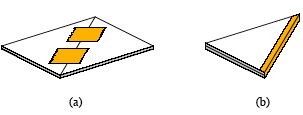
Fig. 4 The
construction of a hinge
These
hinges will allow motions of the two joined faces between 0° and 180° as shown
in Figure 5. It is impossible (and unnecessary here) to make the angle between
the joined faces more than 180°.
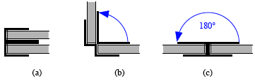
Fig. 5
Range of a hinge
Now a
word of caution. You cannot tape all the connected edges by hinges in the
manner depicted in Figure 4, because it is impossible to open and close every
edge of the finished model in an arbitrary way. Therefore think before taping.
Our procedure (you may find a better one) is to first tape each layer
separately - this is no problem. Then we tape one of the four equatorial hinges
connecting the two layers. The taping of the remaining three hinges of the equator
is more sophisticated, since these are the hinges that now won't open in the
manner of Figure 4(a). But with a little forethought and ingenuity you should
be able to manage it - and remember no man, or woman, is born a master.
At this
point you have all the geometrical parts of the octahedron, but the two layers
are like a balloon without air. You have to supply the air - and this is done
by connecting a rubber band to two of the already taped edges - and this
animates the model.
2.3 How to attach the rubber band
What is
required is to attach the rubber band at two more or less opposite points R1 and R2 of the outer borderline
of edges shown on the flat two-layered model as shown in Figure 6.
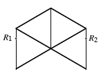
Fig. 6
Points of attachment of the rubber band
To attach
the rubber band at these two points first reinforce the outside hinge along the
edges containing ![]() and
and ![]() with one or two
additional pieces of tape as shown in Figure 7 (a).
with one or two
additional pieces of tape as shown in Figure 7 (a).
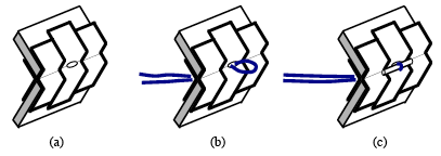
Fig. 7 The
attachment of the rubber band
Next
punch a little hole and pull the rubber band through it (a deformed paper clip
may be used like a crochet hook to do this) as shown in Figure 7 (b). Then lock
the rubber band in place by a small bolt, made of metal (cut a paper clip) or
wood (part of a toothpick) trough it along the edge as shown in Figure 7(c).
Then to affix the bolt cover it with another piece of tape. Finally, attach the
other end of the rubber band (that is, the part of the robber band diametrically
opposite the part of the rubber band already attached) to the other edge. This
will involve stretching the rubber band. It is sometimes useful to pull the
rubber band through the hole by the help of a piece of thread and a needle. You
may need to experiment with rubber bands to get the one of just the right
length. However, after you have made one model you will soon get a sense of how
long, or short, you need the rubber band to be.
When your
model is complete either press it flat onto a table and lift your hand quickly,
or press it flat and toss it into the air. It should pop-up in either case and
make a snapping sound.
3
Other
pop-up polyhedra
The
pop-up octahedron is only one example of a lot of other possibilities of pop-up
polyhedra. We have written about some of them in the Gazette Johnson &
Walser, 1997) and Hilton and Pedersen have made pop-up models with one piece of
cardboard as described in their book (Hilton & Pedersen, 1994). However, we
wish to emphasize that the actual construction of any model is an art and you
may very well discover other ways and other material with which to build pop-up
models of cubes, tetrahedra, as well as other polyhedra. We would be delighted
to hear of any improvement on our method of construction and about any new
models you invent. What you really must do is make these models yourself to
appreciate both their intrinsic beauty and their underlying structure.
Acknowledgment
The
authors would like to thank Jean Pedersen for her helpful suggestions during
the preparation of this manuscript.
References
Hilton, P. and Pedersen, J. (1994) Build
Your Own Polyhedra,
AddisonWesley.
Johnson, S. and Walser, H. (1997)
Pop-Up Polyhedra, The Mathematical Gazette, November, 1997 (to appear).
Cassell, D. (1988) Pop-Up Polyhedra, M. Res 77-79 Mathematics in
School, 17,1
Authors
Scott Johnson (Student), Department of Mathematics, Santa Clara University, Santa Clara, CA 95053, USA
Dr Hans
Walser, Department of
Mathematics, Santa Clara University, Santa Clara, CA 95053, USA
Mathematisches Institut, Basel
University, Rheinsprung 21, CH-4051 Basel