Article published:
Scott Johnson and Hans Walser: Pop-Up Polyhedra. The Mathematical
Gazette. Vol. 81, November 1997, 364-380
Pop-up polyhedra
SCOTT
JOHNSON and HANS WALSER
Introduction
Once upon
a time George Polya showed Jean Pedersen a birthday card sent to him in the
form of a pop-up cube. She studied it and subsequently designed a pop-up octahedron
(the construction for both of these models is described in [1]). (Pedersen soon
discovered that if her models collapsed it reduced the amount of luggage she
had to carry.) With both of these models you can flatten them out, and as soon
as you remove your hand, the model will pop up into its original shape.
We
describe in this article how to construct some new pop-up models of the
platonic solids. We also describe how to construct models that, although they
don't pop up, have other tantalizing features. We then tell how these models
may be used to illustrate vividly some classical theorems about polyhedra. We
give a shorter, more practical, treatment in [2].
In a
final section we give some technical definitions, peculiar to the construction
of these particular collapsible polyhedra, along with some very practical
information about the actual construction of the models.
The
authors wish to thank Jean Pedersen, Santa Clara University, California, for
challenging them to build these models and for very helpful criticism during
the preparation of the manuscript.
A pop-up
model of the edge-jumping cube
In our
first model we have to press two opposite edges to flatten the model (Figure
1).
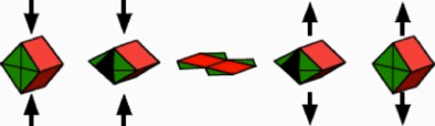
F1GURE 1
Pop-up model of the cube
When the
opposite edges of this cube are pushed towards each other, the vertical faces
will open and we will get the flat situation shown in the centre of Figure 1.
If we release the pressure, the rubber band inside the model, attached at two
opposite paints labeled R (see Figure 2), will pull together so that the cube pops up. If the
model is carefully built, the model will jump into the air.
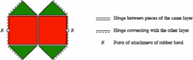
FIGURE 2
One layer
Figure 2
shows one of the two congruent layers of the flattened pop-up cube. A double
line indicates a hinge between two pieces of the same layer and a straight line
alongside a dotted parallel line indicates a hinge-connection with the
congruent second layer. A single straight line indicates the borderline of a
piece, which is not connected to any other piece.
Other
edge-jumping platonic solids
We
learned by experience that models which collapse by pressing and releasing two
opposite edges work very well. Figure 3 shows one each of the two layers of the
edge-jumping octahedron, the edge-jumping icosahedron and the edge-jumping
dodecahedron. The opposite points labeled Ri indicate the attachment of the i-th rubber band.
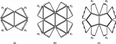
FIGURE 3
Edge-jumping octahedron, icosahedron, dodecahedron
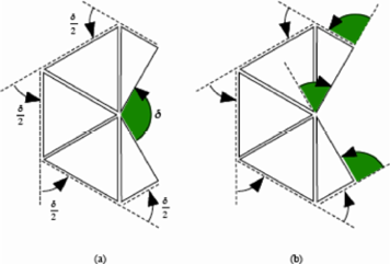
The analogous
edge-jumping model of the tetrahedron is more sophisticated; this is because
opposite edges of a tetrahedron are not parallel. They are in fact orthogonal.
In order to construct an edge-jumping tetrahedron we had to invent a way to
hinge triangles that touch each other only at a vertex. Figure 4 shows both
layers of our model, the top layer seen from outside the tetrahedron, the
bottom layer seen from inside. As you would expect, these two layers have a
position orthogonal to each other. Each layer consists of two trapezia and two
small triangles. The trapezia are hinged by ordinary hinges, but the triangles
have only one vertex in common with the trapezia of the same layer. To hinge
these triangles at a vertex we need what we call 90°-webs. Corresponding hinges
have the same labels. By symmetry we see that these hinges have to lie on the
edges of a square. Each layer is composed of two truncated triangles (trapezia)
and two small triangles, hinged with 90°-webs.
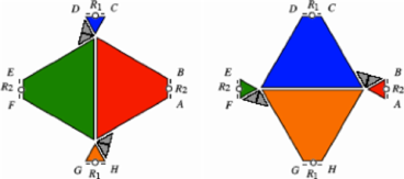
FIGURE 4
Edge-jumping tetrahedron
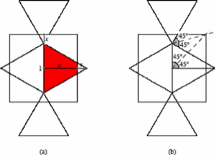
F1GURE 5
The height a of the trapezia
The
question that needs to be answered, of course, is 'precisely what should be the
height of these trapezia?'. To calculate their height a suppose that the edge-length of the
tetrahedron is 1. From Figure 5(a) we see
![]()
hence ![]() . The reader may prove that this height a can be found by using the geometry
of Figure 5(b). The pattern of Figure 6 may provide important clues about
calculating the value of a by other means.
. The reader may prove that this height a can be found by using the geometry
of Figure 5(b). The pattern of Figure 6 may provide important clues about
calculating the value of a by other means.
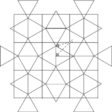
FIGURE 6 A
broader view
Models with
pivots
The
Icosahedron - a face jumper
First, we
describe how to build a model of the icosahedron where we have to press
together two opposite faces to flatten the model. Let these two opposite faces
be the triangle in the middle and the big framing triangle of the Schlegel
diagram (A Schlegel diagram of a polyhedron shows what you would 'see' (that
is, the connectivity of edges and vertices and the arrangement of faces) if you
looked through one face of the model at very close range.) of Figure 7. We
divide the set of the 20 triangles of the surface of the icosahedron into two
subsets of ten triangles. Each of these two subsets leads to a layer of Figure
8(a).
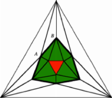
FIGURE 7
Schlegel diagram of the icosahedron
F1GURE 8
Layers of the icosahedron
Since two
opposite faces of the icosahedron are rotated relative to each other by 60°,
the two layers are rotated as well. Thus, superimposing the two layers gives a
repeated star-of-David-like situation shown in Figure 8(b). In the popped-up
situation, the edges AB and A'B'
should coincide. This condition can be achieved by hinging additional hidden
triangles to these edges, and connecting these two triangles by brads (brass
fasteners) at their centers (see Figure 9, where a brad goes through two layers
at point P).
This pop-up model will have six of these hidden pivots. The brads at the three
pairs of opposite pivots can be used for the attachment of three rubber bands.
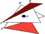
FIGURE 9
Pivot P
The cube - a
vertex jumper
Now we
describe how to build a model of the cube where we have to press together two
opposite vertices to flatten the model. This model may be the hardest one to
make. We begin by thinking of cutting the cube by the plane perpendicular to
the diagonal RS
(as shown in Figure10); the intersection of this plane with the cube is a
regular hexagon. One half of the surface of the cube leads to the layout of one layer of our desired
model (Figure 11(a)).
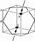
FIGURE 10
Two opposite vertices R and S
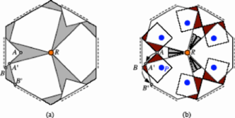
FIGURE 11
One layer of our cube with webs and pivots
In the
centre R of the layer we need three 30°-webs. The layout of the three
right-angled isosceles triangles is such that the 6 borderline hinges lie
symmetrically on the edges of a regular hexagon in the flattened situation. In
the popped-up situation, the edges AB and A'B' should coincide. This can be achieved by
hinging two small squares to each triangle and pivoting them to the big
pentagons. The location of those squares and of the pivot is shown in Figure
12.
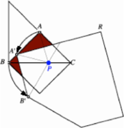
FIGURE 12
The position of the pivot P
The pivot
P is situated on
the diagonal BC
such that the triangle AA'P is equilateral. The triangle BB'P is also equilateral.
The
second layer has the same shape, but is rotated by 60°. Every triangle of the
top layer is hinged with a pentagon of the bottom layer. Thus we get a model
with 12 visible pivots.
Spiral
models
In the
models we have seen so far the top layer does not turn relative to the bottom
layer during the pressing (or collapsing) procedure. We will now show how to
build models where each of the two layers rotate as they collapse and expand.
These models are not activated by rubber bands, instead they are brought into
place by pulled strings.
The spiral
icosahedron
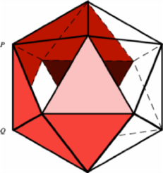
In Figure
13 we see an icosahedron as viewed from above (with some of its faces
transparent). The top triangle is paler red, the bottom triangle dark red. The
six red triangles form a spiral sequence of equilateral triangles running
between the top face and the bottom face. Since we have, not counting the top
and bottom triangles, 18 triangles remaining, we can, in theory, form three
spiral sequences of triangles in this way. We are fortunate that the geometry
allows these spirals to fit together to form the icosahedron. This gives us a
model with two layers (Figure 14); the two layers are hinged as indicated by
labels.
F1GURE 13
A spiral sequence of faces
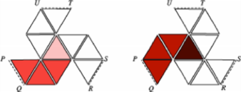
FIGURE 14
The two layers
When we
first constructed this model, we hoped that, by lifting the central triangle of
the top layer, gravity would force the model into the shape of the icosahedron.
Surprisingly, we got a right triangular prism with spiral holes on the surface
(Figure 15). We had to install a sophisticated system of strings, which pull
the vertices of the model into the desired position of the icosahedron (Figure
16).
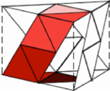
FIGURE 15
Right triangular prism
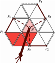
FIGURE 16
The three strings of the top layer
In each
layer, three strings are attached in the points F1, F2, F3, go through a ring R1, R2, R3 respectively, and exit
the model through a central hole H, reinforced by a washer, in the middle of the
top face. Here, the three strings of the top layer may be knotted together. A
corresponding system of three strings has to be installed in the bottom layer.
Starting with the flattened model and pulling at the two opposite knots, the
two opposite central faces will turn by 60° and the icosahedron emerges as if
by magic.
The spiral
dodecahedron
Building
the spiral dodecahedron involved us with 'two-way hinges' (which are explained
later). These two-way hinges are indicated by a straight line alongside a wavy
line in Figure 17. The two-way hinges join the ten bisected lateral pentagonal
faces of the dodecahedron.
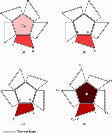
F1GURE 17
The four layers of the spiral dodecahedron
The
flattened model consists of four layers: the top layer (Figure 17(a)) connected
by an ordinary hinge to the second layer (Figure 17(b)), connected by a two-way
hinge to the third layer (Figure 17(c)), connected by an ordinary hinge to the
bottom layer (Figure 17(d)). The five pulling strings of the one side are
attached at the points F1, F2, F3, F4, F5 on the bottom layer and exit the dodecahedron through the
hole H in the
centre of the top pentagon and are knotted together. Pulling the two opposite
knots forces the two opposite pentagonal faces of the dodecahedron to rotate by
36° and finally the dodecahedron materializes.
The spiral
octahedron
Using a
method similar to that used in the construction of the spiral icosahedron and
dodecahedron, we can build a spiral octahedron (Figure 18). The notation here
is the same as for the spiral dodecahedron. Here when we pull the two opposite
knots, the opposite triangular faces of the octahedron rotate by 60°.
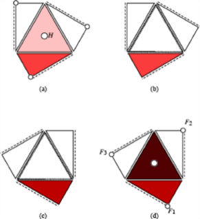
FIGURE 18
The spiral octahedron
We
challenge the reader to find a corresponding spiral cube - we were not
successful in our attempts to do so!
The spiral
tetrahedron
Since the
tetrahedron has no opposite faces, we decided to be content if we could build a
spiral tetrahedron using opposite edges as pressure points. We were successful.
In Figure
19 we see the four layers of this spiral tetrahedron. The two half triangles of
the second layer (Figure 19(b)) are not hinged together, but hinged by two-way
hinges to the half triangles of the third layer (Figure l9(c)). In the
flattened situation, the two opposite edges are parallel. If we pull the model
out (holding it by vertices of opposite edges), these two opposite edges
rotate, relative to each other, by 90°. This is surprisingly pleasing to the
tactile senses.
FIGURE 19
The spiral tetrahedron
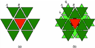
Other models
In all
our models, the rotational symmetry with respect to an axis connecting the
midpoints of the two opposite constituent parts (Of course the mid-point of a
vertex is the vertex itself!) is preserved during the procedures of flattening
and releasing. If we do not insist on such symmetries, we can build even
simpler pop-up models. For example, Figure 20(a) shows one layer of a very
simple model of a pop-up tetrahedron. To flatten this tetrahedron, we simply
press together the two adjacent vertices, which are the ends of the open edge.
In Figure 20(b) we see one layer of the similar model for the octahedron.
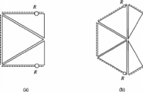
FIGURE 20
Pop-up tetrahedron and octahedron
The total
angular deficiency
The
angular deficiency of a vertex of a polyhedron is the difference between 2π
(i.e. 360°) and the sum of the face angles at this vertex. Thus every vertex of
the cube has an angular deficiency of ![]() , and every vertex of the tetrahedron has an angular
deficiency of
, and every vertex of the tetrahedron has an angular
deficiency of ![]() . The total angular deficiency (D) of a
polyhedron is the sum of the angular deficiencies over all vertices of the
polyhedron. The total angular deficiency is a topological invariant; for a
polyhedron homeomorphic to the sphere we get
. The total angular deficiency (D) of a
polyhedron is the sum of the angular deficiencies over all vertices of the
polyhedron. The total angular deficiency is a topological invariant; for a
polyhedron homeomorphic to the sphere we get ![]() . (Check this with some examples!) The total angular deficiency
of a polyhedron was first studied by René Descartes.
. (Check this with some examples!) The total angular deficiency
of a polyhedron was first studied by René Descartes.
We may
use our pop-up models to illustrate and calculate the total angular deficiency D in some special cases. As an example we take
the popup octahedron of Figure 20(b). The angular deficiency ![]() of the top
vertex is clearly visible (Figure 21(a)). An external angle at a vertex of the
'equator' is half the angular deficiency of this vertex.
of the top
vertex is clearly visible (Figure 21(a)). An external angle at a vertex of the
'equator' is half the angular deficiency of this vertex.
F1GURE 21
The angular deficiency ![]()
The
angular deficiency ![]() of the top
vertex is the algebraic sum of the three shaded external angles shown in Figure
21(b). Notice that the external angle in the middle is negative. Considering
also the bottom vertex of the octahedron, we may see that the total angular
deficiency
of the top
vertex is the algebraic sum of the three shaded external angles shown in Figure
21(b). Notice that the external angle in the middle is negative. Considering
also the bottom vertex of the octahedron, we may see that the total angular
deficiency ![]() of the
octahedron is twice the sum of the external angles of the perimeter of the
flattened pop-up octahedron. Since every external angle of a closed polygon is
the 'deficiency' (the supplement) of the corresponding internal angle, the sum
of the external angles can be considered as the analogue of the total angular
deficiency of a polyhedron. The sum of the external angles of a closed polygon
is also a topological invariant. In our case of a simply closed polygon it is
2π. We demonstrate this in familiar terms by thinking of the long nose of
Pinocchio. When Pinocchio makes a round trip along the boundary of the polygon,
his nose rotates through an angle of precisely 2π (Figure 22).
of the
octahedron is twice the sum of the external angles of the perimeter of the
flattened pop-up octahedron. Since every external angle of a closed polygon is
the 'deficiency' (the supplement) of the corresponding internal angle, the sum
of the external angles can be considered as the analogue of the total angular
deficiency of a polyhedron. The sum of the external angles of a closed polygon
is also a topological invariant. In our case of a simply closed polygon it is
2π. We demonstrate this in familiar terms by thinking of the long nose of
Pinocchio. When Pinocchio makes a round trip along the boundary of the polygon,
his nose rotates through an angle of precisely 2π (Figure 22).
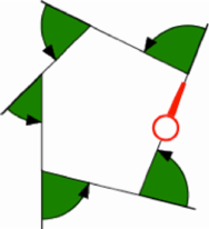
FIGURE 22
The round-trip of Pinocchio
Thus, our
models can be used to display a relationship between two topological invariants,
one concerning the total angular deficiency of a polygon in the plane, the
other concerning the total angular deficiency of a polyhedron in space. The
invariant 'pops up' changing the dimension from two to three. Such
relationships between an area and its perimeter occur also in the formulae of
Stokes, Green and Gauss-Bonnet.
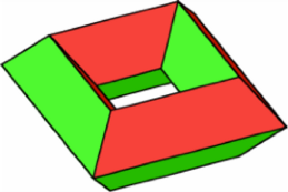
FIGURE 23
Torus
Since the
total angular deficiency is a topological invariant, it should be interesting
to look at a polyhedron of another genus, for instance, at a torus (Figure 23).
Figure 24 shows one layer of a pop-up model of a torus. If you want to build
this model, use thin cardboard for the inner part, not foamboard. Otherwise you
will share with the authors some interesting insights in the topic of
non-convexity.
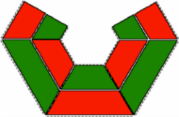
FIGURE 24
One layer of the pop-up torus
Now, to
examine the total angular deficiency of this torus, we manipulate the perimeter
of the flattened model. First we cut the figure into two parts (Figure 25(a)).
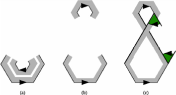
FIGURE 25
The total angular deficiency of the torus
Next we
move the inner part to another position (Figure 25(b)). Finally, we connect the
two parts by straight lines. A straight line does not change anything
concerning external angles. Now we have a polygon in the shape of a figure of
eight (Figure 25(c)) and such a polygon has zero for the sum of its external
angles. This is true because for every positive external angle there is an
equivalent negative one (or, think of Pinocchio's nose as he skates this figure
of eight!). Hence the total angular deficiency D of our
torus is clearly seen to be zero.
Technical
definitions and practical hints
We built
our models from foamboard (foam, 5mm thick, with a paper covering on both
sides), and sometimes from cardboard. For cutting the foamboard we got best results
using a surgeon's scalpel or a sharp pocket knife.
Figure 26
shows how we made an ordinary one-way hinge. We first taped the two parts on
the inner side with pieces of fiberglass-reinforced tape, then closed the hinge
and taped the back of the two parts. These hinges allow motions between 0° and
180° (Figure 27); it is not possible to open more than 180°.
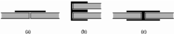
FIGURE 26
An ordinary hinge
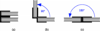
FIGURE 27
Range of an ordinary hinge
Some
models require hinges with a greater range of motion. These sophisticated two-way
hinges require
tapes with alternating sticky sides, made from two pieces of one-side-sticky
tape, as shown in Figure 28. The two-way hinge is then built by the alternate
attachment of such tapes (Figure 29). A two-way hinge allows motions between 0°
and 360°.
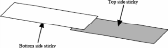
FIGURE 28
Tape for a two-way hinge
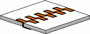
FIGURE 29
Two-way hinge
To affix a rubber band to a hinge, we first reinforce the outside of the hinge by one or two additional reinforced pieces of tape (Figure 30(a)). Then we punch a little hole, pull the rubber band through it (Figure 30(b)) and lock the rubber band with a small wire bolt (wire from paper clips will work, as shown in Figure 30(c)). Finally, we affix the bolt with another piece of tape. For the attachment of the other end of the rubber band, where the rubber band has to be stretched, it is useful to pull the rubber band through the hole with the help of a piece of thread, or a crochet hook.
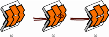
FIGURE 30
Attachment of a rubber band
Pivots
are made by one (Figure 31(a)) (or two (Figure 31(b))) additional hidden faces
made from cardboard (foamboard will be too thick for this purpose). The pivot
itself is an ordinary brad.
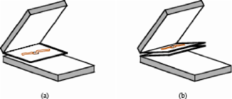
FIGURE 31
Pivots
In some
models the pressing procedure separates two or more pieces such that they have
no edge, i.e. no hinge, in common, but only a vertex. To construct such
'zero-dimensional hinges' we use webs. We got the inspiration for these zero-dimensional
hinges from observing the webs between the claws of a water bird (Figure 32).
Our webs are made from cardboard and move inwards when the model pops up.
Figure 33 shows the situation where webs are attached to three squares (this
situation may occur at a vertex of a cube). We have three 30°-webs, each
consisting of two triangles with an angle of 15° and a hinge in between
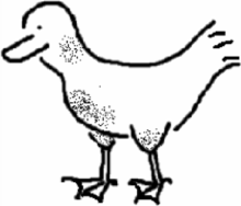
FIGURE 32
Web
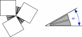
FIGURE 33
Web connection
References
1. Peter
Hilton and Jean Pedersen, Build your own polyhedra, Addison Wesley, Menlo Park,
California, (1994).
2. Scott
Johnson and Hans Walser, The pop-up octahedron, Mathematics in School 26
(November 1997).
SCOTT JOHNSON Student at Santa Clara
University, Santa Clara, Calilornia 95053, USA
HANS WALSER Santa Clara University,
Santa Clara, Calilornia 95053, USA and Mathematik-Departement, Universität
Basel, Rheinsprung 21, CH-4051 Basel